An up-down counter is a combination of an up-counter and a down-counter. It can count in both directions, increasing as well as decreasing.
A mode control input(M) is used to select either up or down mode.
we have the M(mode control) input which decides whether  or
or  should be the clock
input to the next flip flop. We have to design a combinational circuit, that when applied M = 0 gives up counting and when M = 1 gives down counting.
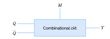
The combination of inputs to the combinational circuit that we have to design and the corresponding output it should produce is given below. The equation for Y can be found out using K-Map.
 |
|
|
 |
|---|---|---|---|
| 0 | 0 | 0 | 0 |
| 0 | 0 | 1 | 0 |
| 0 | 1 | 0 | 1 |
| 0 | 1 | 1 | 1 |
| 1 | 0 | 0 | 0 |
| 1 | 0 | 1 | 1 |
| 1 | 1 | 0 | 0 |
| 1 | 1 | 1 | 1 |
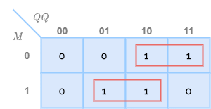
Hence from the k-map, we got the equation in sum-of-product terms as  .
.
A 4 bit up/ down counter can be designed as follows.
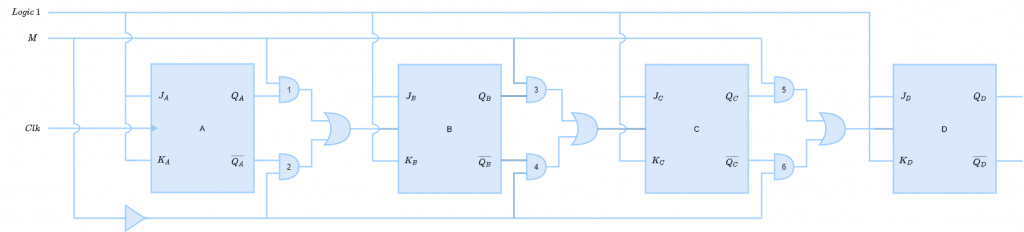
AND gates 1, 3 and 5 has one input connected with  input and the other input from Q
output of flip flop preceding it. Similarly, gates 2, 4 and 6 have input from M and  .
.
- When M = 0, gates 1, 3 and 5 gives Q as output and gates 2, 4 and 6 gives 0.
- When these outputs are given to OR gate, it produces Q as output, which is connected to the clock input of next flip flop.
- Hence, we have up counting.
- When M = 1, gates 1, 3 and 5 gives 0 as output and gates 2, 4 and 6 gives Q as output.
- When these outputs are given to OR gate, it produces Q as output, which is connected to the clock input of next flip flop.
- Hence, we have down counting.