
Counters in which the flip-flops are supplied with different clock signals. The first flip-flop is clocked by the external clock pulse and then each successive flip-flop is clocked by the output of the preceding flip-flop.
2-bit Asynchronous Up Counter
The logic diagram of a 2-bit asynchronous up counter using JK flip-flop is shown in the figure.
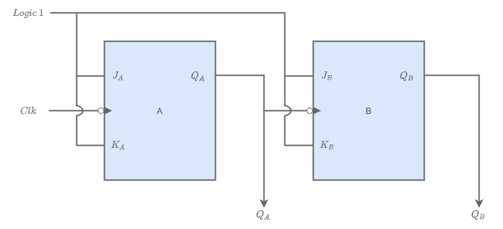
The J and K inputs of 2 flip flops are connected to logic 1. An external clock is applied to flip-flop A and its output QA is applied to flip-flop B as the clock input. At the negative-going edge of each clock pulse, flip-flop A changes its state. Flipflop B changes state only when triggered by a negative-going transition of the QA output of flipflop A. The truth table and timing diagram are given below.
| Clock |  |  | Decimal Equivalent |
|---|---|---|---|
| Initially | 0 | 0 | 0 |
| ???? | 0 | 1 | 1 |
| ???? | 1 | 0 | 2 |
| ???? | 1 | 1 | 3 |
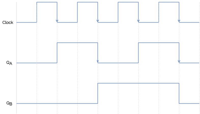
From the timing diagram, it is clear that
- Initially, the flip flops store zero.
- When the negative edge of first clock pulse arrives, QA toggles from 0 to 1. Since a positive edge of QA doesn’t toggle flip flop B, QB remains at 0.
- Hence, we got a transition from 00 -> 01 (QBQA).
- Similarly, on the next clock pulse the counter goes to state 10, then 11, and after that it goes back to sate 00.
As a result, it counted four states (from 0 to 3).
3-bit Asynchronous Up Counter
The logic diagram of a 3-bit asynchronous up counter using JK flip-flop is shown in the figure.
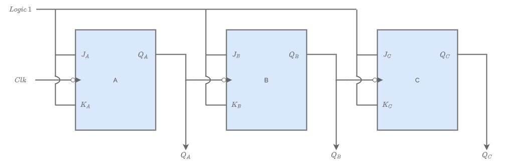
It works exactly the same way as a two-bit asynchronous binary counter mentioned above, except it
has eight states due to the third flip-flop. The truth table and timing diagram are given below.
| Clock |  | | | Decimal Equivalent |
|---|---|---|---|---|
| Initially | 0 | 0 | 0 | 0 |
| ???? | 0 | 0 | 1 | 1 |
| ???? | 0 | 1 | 0 | 2 |
| ???? | 0 | 1 | 1 | 3 |
| ???? | 1 | 0 | 0 | 4 |
| ???? | 1 | 0 | 1 | 5 |
| ???? | 1 | 1 | 0 | 6 |
| ???? | 1 | 1 | 1 | 7 |
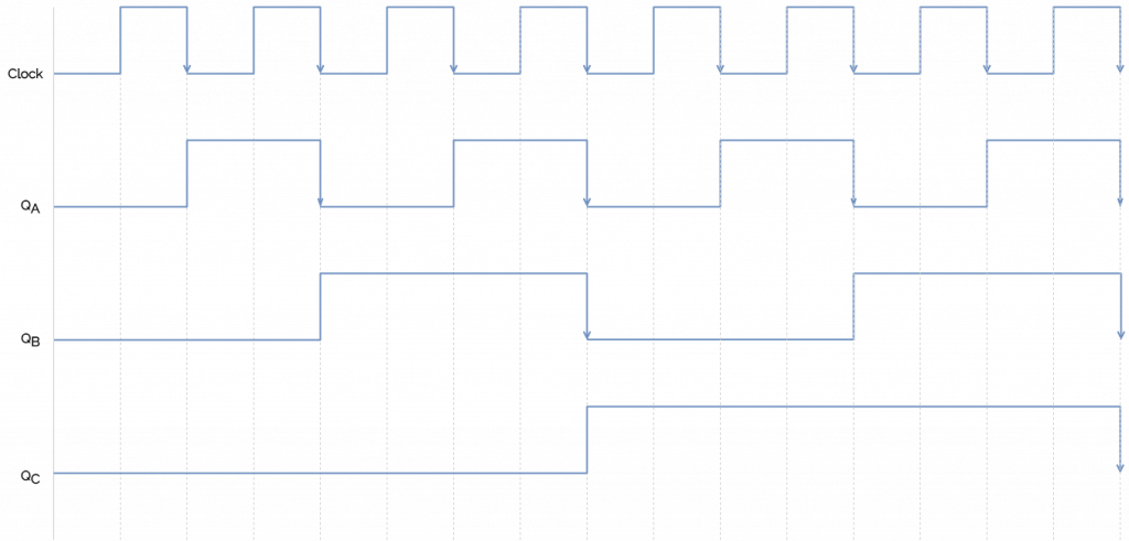
- Initially, all the flip flops store zero.
- When the negative edge of first clock pulse arrives, QA toggles from 0 to 1.
- Since a positive edge of QA doesn’t toggle flip flop B, QB remains at 0.
- Also, since a positive edge of QB doesn’t toggle flip flop C, QC remains at 0.
- Hence, we got a transition from 000 -> 001 (QCQBQA).
- Similarly, on the next clock pulse the counter goes to state 010, then 011, and so on.
- The counter gets to a state 111 after which it goes back to sate 000.
- Hence, it counted eight states (from 0 to 7).
4-bit Asynchronous Up Counter
The logic diagram of a 4-bit asynchronous up counter using JK flip-flop is shown in the figure.
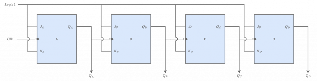
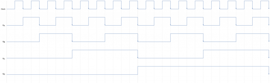
Here, we have 4 flip flops, and the number of states is 16, from 0000 – 1111 (0 to 15). The truth table and timing diagram are given below.
| Clock | | | | | Decimal Equivalent |
|---|---|---|---|---|---|
| Initially | 0 | 0 | 0 | 0 | 0 |
| ???? | 0 | 0 | 0 | 1 | 1 |
| ???? | 0 | 0 | 1 | 0 | 2 |
| ???? | 0 | 0 | 1 | 1 | 3 |
| ???? | 0 | 1 | 0 | 0 | 4 |
| ???? | 0 | 1 | 0 | 1 | 5 |
| ???? | 0 | 1 | 1 | 0 | 6 |
| ???? | 0 | 1 | 1 | 1 | 7 |
| ???? | 1 | 0 | 0 | 0 | 8 |
| ???? | 1 | 0 | 0 | 1 | 9 |
| ???? | 1 | 0 | 1 | 0 | 10 |
| ???? | 1 | 0 | 1 | 1 | 11 |
| ???? | 1 | 1 | 0 | 0 | 12 |
| ???? | 1 | 1 | 0 | 1 | 13 |
| ???? | 1 | 1 | 1 | 0 | 14 |
| ???? | 1 | 1 | 1 | 1 | 15 |
3-bit Asynchronous Down Counter
An asynchronous down counter is designed the same way as an up counter with a few corrections.
The inputs for JK flip flops are maintained at logic 1. Here the flip flops other than the first one is
triggered by  outputs of preceding flip flops. The counter output is taken as QC QB QA itself.
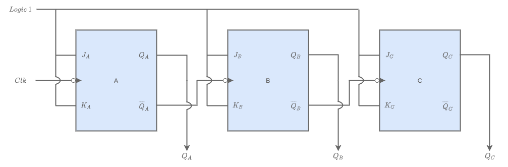
The counter designed thus counts in reverse order, from 7 to 0 as follows.
| Clock | | | | Decimal Equivalent |
|---|---|---|---|---|
| ???? | 1 | 1 | 1 | 7 |
| ???? | 1 | 1 | 0 | 6 |
| ???? | 1 | 0 | 1 | 5 |
| ???? | 1 | 0 | 0 | 4 |
| ???? | 0 | 1 | 1 | 3 |
| ???? | 0 | 1 | 0 | 2 |
| ???? | 0 | 0 | 1 | 1 |
| ???? | 0 | 0 | 0 | 0 |
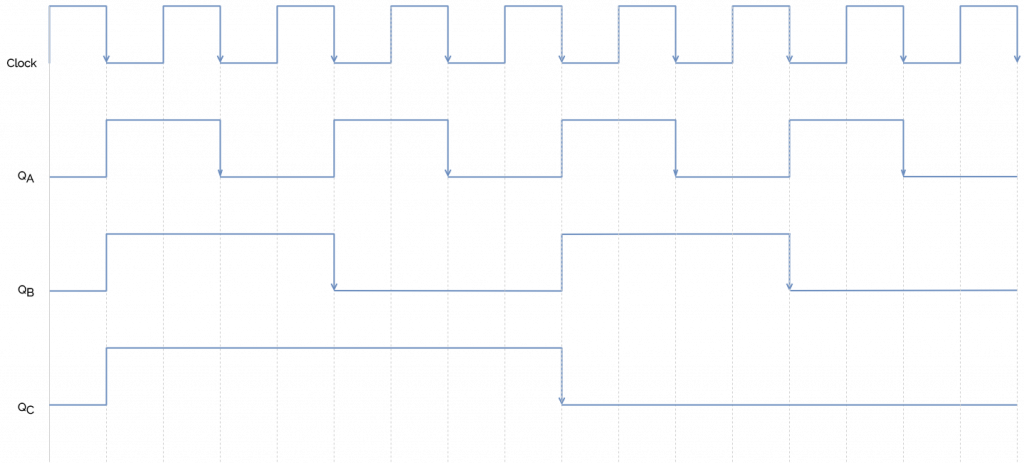
- Initially, all flip flops store zero, hence, the complemented output will be 1.
- When the first clock pulse arrives, the negative edge triggers flip flop A and the output goes from 0 to 1. The complimented output goes from 1 to 0 at the same time.
- Since it triggers flip flop B, the negative edge toggles QB from 0 to 1.
- Similarly, negative edge of complement output of B toggles QC from 0 to 1.
- Now, we have 111, which equals 7.
- On the next clock pulse, we have a state change 111 -> 110, then 110 -> 101 and so on.
When the state 000 is reached, the next clock pulse will toggle all outputs to 111. Hence it counts from 7 to 0.